During the unwrapping process, the vertices of the 3D model are mapped into a two-dimensional coordinate system. This new coordinate system is known as the UV Coordinate System.
The UV Coordinate System is composed of two axes, known as U and V axes. These axes are equivalent to the familiar X-Y axes; the only difference is that the U-V axes range from 0 to 1. The U and V components are also referred as S and T components.
The new vertices produced by the unwrapping of the model are called UV Coordinates. These coordinates will be loaded into the GPU. And will serve as reference points to the GPU as it attaches the texture to the model.
Luckily, you do not need to compute the UV coordinates. These coordinates are supplied by modeling software tools, such as Blender.
Decompressing Image Data
For the fragment shader to apply a texture, it needs the RGBA color information of an image. To get the raw data, you will have to decode the image. There is an excellent library capable of decoding ".png" images known as LodePNG created by Lode Vandevenne. We will use this library to decode a png image.
Texture Filtering & Wrapping (Addressing)
Textures don't always align with a 3D model. Sometimes, a texture needs to be stretched or shrunk to fit a model. Other times, texture coordinates may fall out of range.
You can inform the GPU what to do in these instances by setting Filtering and Wrapping Modes. The Filtering Mode lets you decide what to do when pixels don't have a 1 to 1 ratio with texels. The Wrapping Mode allows you to choose what to do with texture coordinates that fall out of range.
Texture Filtering
As I mentioned earlier, there is never a 1 to 1 ratio between texels in a texture map and pixels on a screen. For example, there are times when you need to stretch or shrink a texture as you apply it to the model. This will break up any initial correspondence between a texel and a pixel. Because of this, the color of a pixel needs to be approximated to the closest texel. This process is called Texture Filtering.
Note: Stretching a texture is called Magnification. Shrinking a texture is known as Minification.
The two most common filtering settings are:
- Nearest Neighbor Filtering
- Linear Filtering
Nearest Neighbor Filtering
Nearest Neighbor Filtering is the fastest and simplest filtering method. UV coordinates are plotted against a texture. Whichever texel the coordinate falls in, that color is used for the pixel color.
Linear Filtering
Linear Filtering requires more work than Nearest Neighbor Filtering. Linear Filtering works by applying the weighted average of the texels surrounding the UV coordinates. In other words, it does a linear interpolation of the surrounding texels.
Texture Wrapping
Most texture coordinates fall between 0 and 1, but there are instances when coordinates may fall outside this range. If this occurs, the GPU will handle them according to the Texture Wrapping mode specified.
You can set the wrapping mode for each (s,t) component to either Repeat, Clamp-to-Edge, Mirror-Repeat, etc.
- If the mode is set to Repeat, it will force the texture to repeat in the direction in which the UV-coordinates exceeded 1.0.
- If it is set to Mirror-Repeat, it will force the texture to behave as a Repeat mode but with a mirror behavior; thus flipping the texture.
- If it is set to Clamp-to-Edge, it will force the texture to be sampled along the last row or column with valid texels.
Metal has a different terminology for Texture Wrapping. In Metal, it is referred to as "Texture Addressing."
Applying Textures using Metal
To apply a texture using Metal, you need to create two objects; a Texture and a Sampler State object.
The Texture object contains the image data, format, width, and height. The Sampler State object defines the filtering and addressing (wrapping) modes.
Texture Object
To apply a texture using Metal, you need to create an MTLTexture object. However, you do not create an MTLTexture object directly. Instead, you create it through a Texture Descriptor object, MTLTextureDescriptor.
The Texture Descriptor defines the properties, such as image width, height and image format.
Once you have created an MTLTexture object through an MTLTextureDescriptor, you need to copy the image raw data into the MTLTexture object.
Sampler State Object
As mentioned earlier, the GPU needs to know what to do when a texture does not fit a 3D model properly. A Sampler State Object, MTLSamplerState, defines the filtering and addressing modes.
Just like a Texture object, you do not create a Sampler State object directly. Instead, you create it through a Sampler Descriptor object, MTLSamplerDescriptor.
Setting up the project
Let's apply a texture to a 3D model.
By now, you should know how to set up a Metal Application and how to render a 3D object. If you do not, please read the prerequisite articles mentioned above.
For your convenience, the project can be found here. Download the project so you can follow along.
Note: The project is found in the "addingTextures" git branch. The link should take you directly to that branch.
Let's start,
Declaring attribute, texture and Sampler objects
We will use an MTLBuffer to represent UV-coordinate attribute data as shown below:
// UV coordinate attribute
id<MTLBuffer> uvAttribute;
To represent a texture object and a sampler state object, we are going to use MTLTexture and MTLSamplerState, respectively. This is shown below:
// Texture object
id<MTLTexture> texture;

//Sampler State object
id<MTLSamplerState> samplerState;
Loading attribute data into an MTLBuffer
To load data into an MTLBuffer, Metal provides a method called "newBufferWithBytes." We are going to load the UV-coordinate data into the uvAttribue buffer. This is shown in the "viewDidLoad" method, line 6c.
//6c. Load UV-Coordinate attribute data into the buffer
uvAttribute=[mtlDevice newBufferWithBytes:smallHouseUV length:sizeof(smallHouseUV) options:MTLResourceCPUCacheModeDefaultCache];
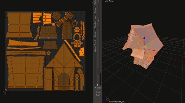
Decoding Image data
The next step is to obtain the raw data of our image. The image we will use is named "small_house_01.png" and is shown below: