Let's learn how to render 3D objects using the Metal API. Before I start, I recommend you to read the prerequisite materials listed below:
Prerequisite:
- Before using Metal: Computer Graphics Basics
- Getting Started with Metal
- Rotating a 2D object in Metal
Coordinate Systems
In Computer Graphics, we work with several coordinate systems. The most popular coordinate systems are:
- Object Space
- World Space
- Camera (view) Space
- Perspective & Orthogonal Projection Spaces
Object Space
In Object Space, the vertices composing the mesh are defined relative to the mesh origin point, usually (0,0,0).

World Space
In World Space, the mesh's position is defined relative to the world's origin point. In this instance the object is located five units along the x-direction from the world's origin point.

Camera Space
In Camera Space, the world's position is defined relative to the camera's (view) origin point.

Perspective & Orthogonal Projection Space
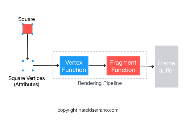
There are two ways to set up a Projection Space. It can be configured with an Orthogonal-Projection, thus producing a 2D image on the framebuffer, as shown below:

Or it can be set with a Perspective Projection, thus generating a 3D image on the framebuffer, as illustrated below:

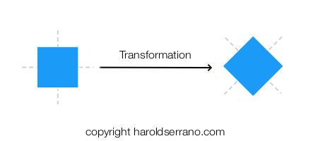
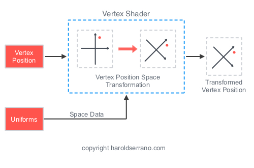
Transformations
Matrices allow you to transform an object, such as rotating or scaling the object. However, matrices also enable you to transform coordinate systems.
To render a 3D object, you must transform an object's coordinate system into the following coordinate systems before it ends up in the framebuffer:
- World-Space Transformation
- Camera-Space Transformation
- Perspective-Projective Space Transformation
Mathematically, you transform coordinate systems by multiplying the space matrices.
World-Space Transformation
In this transformation, the World's matrix transforms the object's coordinate system. The object's position is now defined relative to the world's origin.
This transformation is called Model-World Transformation or Model-Transformation.

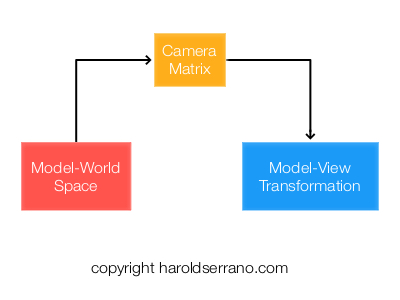
Camera-Space Transformation
In this step, the Camera matrix transforms the Model-World's coordinate system. The world's position is now defined relative to the camera's origin.
This transformation is known as the Model-View Transformation
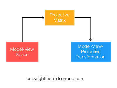
Perspective-Projection Transformation
The Perspective projection matrix transforms the Model-View coordinate system, thus creating the illusion of depth.
This transformation is known as the Model-View-Projection transformation.
And that is it. One of the concepts that differ between rendering a 2D vs. a 3D object are the transformations performed.
Setting up the Application
Let's render a simple 3D cube using Metal.
By now, you should know how to set up a Metal Application and how to render a 2D object. If you do not, please read the prerequisite articles mentioned above. In this article, I will focus on setting up the transformations and shaders.
For your convenience, the project can be found here. Download the project so you can follow along.
Note: The project is found in the "rendering3D" git branch. The link should take you directly to that branch.
Let's start,
Open up the "ViewController.m" file.
Setting up the Cube vertices and indices
A cube is composed of eight vertices as shown below:
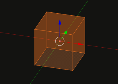
The vertices representing the cube is defined as follows:
static float cubeVertices[] =
{
    -0.5, 0.5, 0.5,1,
    -0.5,-0.5, 0.5,1,
    0.5,-0.5, 0.5,1,
    0.5, 0.5, 0.5,1,

    -0.5, 0.5,-0.5,1,
    -0.5,-0.5,-0.5,1,
    0.5,-0.5,-0.5,1,
    0.5, 0.5,-0.5,1,

};
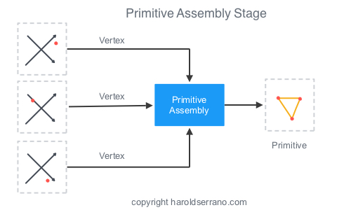
In computer graphics, a mesh is a collection of vertices, edges, and faces that define the shape of a 3D object. The most popular type of polygon primitive used in computer graphics is a Triangle primitive.
Before you render an object, it is helpful to Triangularize the object. Triangularization means to break down the mesh into sets of triangles as shown below:

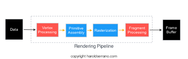
It is also helpful to obtain the relationship between a vertex and a triangle. For example, a vertex can be part of several triangles. The relationship between a vertex and a triangle primitive is known as "Indices," and they inform the Primitive Assembly, in the Rendering Pipeline, how to connect the triangle primitives.
The "indices" we will provide to the rendering pipeline are defined below:
const uint16_t indices[] = {
    3,2,6,6,7,3,
    4,5,1,1,0,4,
    4,0,3,3,7,4,
    1,5,6,6,2,1,
    0,1,2,2,3,0,
    7,6,5,5,4,7
};
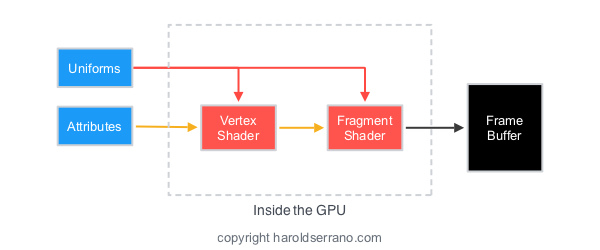
Declaring Attribute and Uniform data
In Metal, An MTLBuffer represents an allocation of memory that can contain any type of data. We will use an MTLBuffer to represent vertex and indices attribute data as shown below:
//Attributes
id<MTLBuffer> vertexAttribute;

id<MTLBuffer> indicesBuffer;
We will also use an MTLBuffer to represent our Model-View-Projection uniform:
//Uniform
id<MTLBuffer> mvpUniform;
Loading attribute data into an MTLBuffer
To load data into an MTLBuffer, Metal provides a method called "newBufferWithBytes." We are going to load the cube vertices and indices into the vertexAttribute and indicesBuffer as shown below. This is shown in the "viewDidLoad" method, Line 6.
//6. create resources

//load the data attribute into the buffer
vertexAttribute=[mtlDevice newBufferWithBytes:cubeVertices length:sizeof(cubeVertices) options:MTLResourceOptionCPUCacheModeDefault];

//load the index into the buffer
indicesBuffer=[mtlDevice newBufferWithBytes:indices length:sizeof(indices) options:MTLResourceOptionCPUCacheModeDefault];
Updating the Transformations
The next step is to compute the space transformations. I could have set up the project to show a static 3D object by only calculating the Model-View-Projection transformation in the "viewDidLoad" method. However, we are going to go a step beyond.
Instead, of producing a static 3D object, we are going to rotate the 3D object as you swipe your fingers from left to right. To accomplish this effect, you will compute the MVP transformation before every render pass.
The project contains a method called "updateTransformation" which is called before each render pass. In the "updateTransformation" method, we are going to rotate the model, and transform its space into a World, Camera, and Projective Space.
Setting up the Coordinate Systems
The model will be rotated as you swipe your fingers. This rotation is accomplished through a rotation matrix. The resulting matrix corresponds to a new model space.
//Rotate the model and produce the model matrix
matrix_float4x4 modelMatrix=matrix_from_rotation(rotationAngle*M_PI/180, 0.0, 1.0, 0.0);
The world's coordinate system will not be translated nor rotated. Mathematically, this coordinate system is represented by an Identity matrix.
//set the world matrix to its identity matrix.i.e, no transformation. It's origin is at 0,0,0
matrix_float4x4 worldMatrix=matrix_identity_float4x4;
The Camera will be positioned three units out into the z-axis.
//Set the camera position in the z-direction
matrix_float4x4 viewMatrix=matrix_from_translation(0.0, 0.0, 3.0);
The Projection-Perspective matrix will be set with a field of view of 45 degrees and with an aspect ratio determined by the width and height of your device's screen.
//compute the projective-perspective matrix
float aspect=self.view.bounds.size.width/self.view.bounds.size.height;

matrix_float4x4 projectiveMatrix=matrix_from_perspective_fov_aspectLH(45.0f * (M_PI / 180.0f), aspect, 0.1f, 100.0f);
Space Transformation
Once we have the coordinate systems, we can transform them. We do this by multiplying their respective matrices.
The snippet below shows the different transformations
//Transform the model into the world's coordinate space
matrix_float4x4 modelWorldTransformation=matrix_multiply(worldMatrix, modelMatrix);

//Transform the Model-World Space into the camera's coordinate space
matrix_float4x4 modelViewTransformation=matrix_multiply(viewMatrix, modelWorldTransformation);

//Transfom the Model-View Space into the Projection space
matrix_float4x4 modelViewProjectionTransformation=matrix_multiply(projectiveMatrix, modelViewTransformation);
Finally, we load the "ModelViewProjection" transformation into the "mvpUniform" buffer.
//Load the MVP transformation into the MTLBuffer
mvpUniform=[mtlDevice newBufferWithBytes:(void*)&modelViewProjectionTransformation length:sizeof(modelViewProjectionTransformation) options:MTLResourceOptionCPUCacheModeDefault];
Linking Resources to Shaders
In the "renderPass" method, we are going to link the vertices attributes and MVP uniforms to the shaders. The linkage is shown in lines 10c and 10d.
//10c. set the vertex buffer object and the index for the data
[renderEncoder setVertexBuffer:vertexAttribute offset:0 atIndex:0];

//10d. set the uniform buffer and the index for the data
[renderEncoder setVertexBuffer:mvpUniform offset:0 atIndex:1];
Note that we set the "vertexAttribute" at index 0 and the "mvpUniform" at index 1. These values will be linked to the shader's argument.
Setting the Drawing command
Earlier I talked about indices and how they inform the rendering pipeline how to assemble the triangle primitives. Metal provides these indices to the rendering pipeline through the Drawing command as shown below:
//10e. Set the draw command
[renderEncoder drawIndexedPrimitives:MTLPrimitiveTypeTriangle indexCount:[indicesBuffer length]/sizeof(uint16_t) indexType:MTLIndexTypeUInt16 indexBuffer:indicesBuffer indexBufferOffset:0];
Setting up the Shaders (Functions)
Open the "MyShader.metal" file.
Take a look at the function "vertexShader." Its argument receives the vertices at buffer 0 and the "mvp" transformation at buffer 1.
vertex float4 vertexShader(device float4 *vertices [[buffer(0)]], constant float4x4 &mvp [[buffer(1)]],uint vid [[vertex_id]]){

    //transform the vertices by the mvp transformation
    float4 pos=mvp*vertices[vid];

    return pos;

}
Within the function, the vertices of the cube get transformed by the "mvp" transformation matrix.
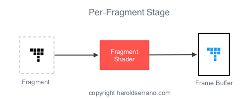
The "fragmentShader" function is simple. It sets the rectangle to the color red.
fragment float4 fragmentShader(float4 in [[stage_in]]){

    //set color fragment to red
    return float4(1.0,0.0,0.0,1.0);

}
And that is it. Build the project. You should see a cube. Swipe your fingers and the cube should rotate.
Note: As of today, the iOS simulator does not support Metal. You need to connect your iPad or iPhone to run the project.
In the next article, I will teach you how to add shading to a 3D mesh so that it looks a lot cooler.
Hope it helps.