Introduction
Light is everything. Without it we could not see the world around us. In a similar fashion, without the simulation of light in computer graphics, we could not see the characters in games. Light is a simulated through OpenGL shaders. Understanding how light is simulated in OpenGL is very important and fortunately, it is not complicated to implement.
In this tutorial, you will learn the basic concepts of light such as:
- Measuring Light
- Type of Lights
- Categories of Light
Once we have created a basic mathematical model for each light category, we will implement these models in shaders to light our 3D model.
Objective
Our objective is to simulate real-world lighting in a mobile device using shaders. This is a hands on project. Feel free to download the template Xcode project and code along.
At the end of this tutorial, you will know how to simulate light in OpenGL and light up a 3D model.

Things to know
In order to get the most out of this tutorial, I suggest to read the following post:
Measuring light
There are three types of measurements used in lighting. They are:
- Lumen- amount of light generated by the light source.
- Illuminance- amount of light that reaches the object from the light source.
- Luminance- amount of light that reaches the observer from the object.
Type of Lights
There are two types of lights; Directional and Point Light. A directional light source is a light that is relatively far away; the sun, for example. A point light source is a near light source; a lightbulb in your room, for example.
Directional Lights
Directional light is a light source that is infinitely far away. A directional light is defined by a point at infinity. For example, relative to the earth, the sun is a directional light source. The light direction vector of a Directional Light source is defined as:
Equation 1. Light Direction vector of a Directional Light

Since a directional light is consider to be infinitely far away, its illuminance is constant all throughout.
Equation 2. Illuminance of a Directional Light

Point Lights
Point light is a light source that is relative close to the object and illuminates equally in all directions. For example, the lightbulb in your room is a Point Light. The Light direction vector of a Point Light is defined as follows:
Equation 3. Light Direction vector of a Point Light

Unlike Directional Light, a Point Light’s illuminance is not constant. Instead, its illuminance approximates a physical property of light known as the Inverse Square Law.
The Inverse Square Law is also known as Distance Attenuation.
The Inverse Square Law for a point light is defined as:
Equation 4. Inverse Square Law of a Point Light

Even though equation 4 is physically correct. It does not lend itself for artistic purposes. Therefore, a more general distance attenuation function is used in rendering systems as OpenGL.
Equation 5. General Distance Attenuation of a Point Light

Material interaction with light
Light needs a surface to interact with. Depending on the surface composition, light behaves differently. For example, wood, gold and diamond react differently to light.
To model these behaviors in a mathematical equation, the surface’s material is taken into account. The material of an object describes how it behaves to the four different categories of light.
Categories of light
There are four different categories of light. They are:
- Emissive Light
- Ambient Light
- Diffuse Light
- Specular Light
A material behaves differently to each of these lights.
Emissive Light
Emissive light is the light produced by the surface itself in the absence of a light source. It is simply the color and intensity which an object glows.
Ambient Light
Ambient light is the light that enters a room and bounces multiple times around the room before lighting a particular object. Ambient light contribution depends on the light’s ambient color and the ambient’s material color.
The light’s ambient color represents the color and intensity of the light. The ambient’s material color represents the overall ambient light the surface reflects.
Mathematically, the ambient term for a given light is as follows:
Equation 6. Ambient Light Equation

Diffuse Light
Diffuse light represents direct light hitting a surface. The Diffuse Light contribution is dependent on the incident angle. For example, light hitting a surface at a 90 degree angle contributes more than light hitting the same surface at a 5 degrees.
Diffuse light is dependent on the material colors, light colors, illuminance, light direction and normal vector.
Mathematically, diffuse light is represented as follows:
Equation 7. Diffuse Light Equation

The max() function simply cuts off any light with an incident angle less than 0 or greater than 180 degrees. In these instances, no diffuse lighting occurs.
Specular Light
Specular light is the white highlight reflection seen on smooth, shinny objects. Specular light is dependent on the direction of the light, the surface normal and the viewer location.
Mathematically, specular light is represented as follows:
Equation 8. Specular Light Equation

where the Reflection Vector is represented as follows:
Equation 9. Reflection Vector

The shininess coefficient > m> controls the size of the highlight. A small value of > m> leads to a larger highlight and vice-versa.
Modeling lights in shaders
Having defined the mathematical models of each light, we are ready to implement them in code. In the fragment shader we will implement four main functions:
- computeAmbientComponent()
- computeDiffuseComponent()
- computeSpecularComponent()
- addAmbientDiffuseSpecularLights()
The first three functions will implement the mathematical model for each light. The fourth function will combine the outputs of all three functions and provide one single color value for the light.
The fragment shader will also contain the function computePointLightValues(). This function will calculate the light direction vector, illuminance and attenuation of the light, as shown in equation 3, 4 and 5.
The fragment shader will also contain a structure data type called Lights. This structure contains the following light information:
- Light direction vector
- Light illuminance
- Light intensity
- Light attenuation
- Color of the light
- Location of the light
The Vertex shader will be quite simple. It will simply contain two varying variables which are used to transform the position of the vertices and vertices normals into model-View Space.
Let’s begin.
Coding the Vertex Shader
Open up the Shader.vsh file. Head to comment line 4 and type what is shown in listing 1.
Listing 1. Declaring varying variables for light
//4. declare varying variables that will provide the vertex position in model-view space
varying mediump vec4 positionInViewSpace;

//5. declare varying variables that will provide the normal position in model-view space
varying mediump vec3 normalInViewSpace;

//6. declare varying position of the light
varying vec4 lightPosition=vec4(5.0,-2.0,5.0,1.0);
Lines 4 & 5 declare the varying variables representing the vertex position and normal vectors, respectively.
Line 6 declares a varying variable for the position of the light.
Now head to comment line 7 and type what is shown in listing 2.
Listing 2. Transforming to model-view space
void main()
{

//7. transform the vertex position to model-view space
positionInViewSpace=modelViewMatrix*position;

//8. transform the normal position to model-view space
normalInViewSpace=normalMatrix*normal;

//9. transform the light position to model-view space
lightPosition=modelViewMatrix*lightPosition;
This is all what is needed in the vertex shader. The bulk of the calculation is done in the fragment shader.
Lines 7-9 simply transform each varying variable to model-view space. The lighting functions defined in the fragment shader requires the vertex position, normal vectors and light position to be transformed to model-view space.
Recall that varying variables are able to flow from vertex shaders to fragment shaders. We are going to transform the variables above in the vertex shader and pass them along to the fragment shader.
Coding the Fragment Shader
The best place to do lighting calculations is in the fragment shader. Although the calculations that follow can be done in the vertex shader, it does not produce a nice aesthetic result. Thus, I recommend that all lighting calculations be done in the fragment shader.
Open up the Shader.fsh file. Head to comment line 3 and type what is shown in listing 3.
Lines 3-5 simple declare the ambient, diffuse and specular material color. These are the color that the 3D model reflects when in contact with a particular light type.
Line 6 declares the shininess factor for the specular light. The higher this value, the smaller the specular highlight and vice-versa.
Listing 3. Declaring the material colors
//3. declare the ambient material color - dark gray
mediump vec4 AmbientMaterialColor=vec4(0.1,0.1,0.1,1.0);

//4. declare the diffuse material color-gray
mediump vec4 DiffuseMaterialColor=vec4(0.5,0.5,0.5,1.0);

//5. declare the specular material color- white
mediump vec4 SpecularMaterialColor=vec4(1.0,1.0,1.0,1.0);

//6. Shininess factor
mediump float Shininess=5.0;
Next, head to comment line 7 and type what is shown in listing 4.
Lines 7-9 simply declare the varying variables previously declared in the vertex shader. Recall that these varying variables will receive their new data from the vertex shader.
Listing 4. Declaring the varying variables
//7. declare varying variable of the light
varying mediump vec4 lightPosition;

//8. declare varying variables that will provide the vertex position in model-view space
varying mediump vec4 positionInViewSpace;

//9. declare varying variables that will provide the normal position in model-view space
varying mediump vec3 normalInViewSpace;
We are going to declare a structure data type for the light. This structure will contain the light properties as illuminance, position, etc.
Head to comment line 10 and type what is shown in listing 5.
Listing 5. Declaring a structure data type for the light
//10. declare a light structure
struct Lights{
mediump vec3 L; // light direction vector
lowp float iL; //light illuminance
float pointLightIntensity; //light intensity
vec3 pointLightAttenuation; //light attenuation
vec3 lightColor; //color of the light
vec4 lightPosition; //position of the light
};

Lights light;
Lines 11-15 declare the functions we will use in the fragment shader. You are going to define each of these functions. Let’s start by defining the computePointLightValues() function.
Computing light direction, illuminance and attenuation
The computePointLightValues() is responsible for calculating the light direction vector, illuminance and attenuation of the light, as shown in equation 3, 4 and 5.
Go to comment line 17 and copy what is shown in listing 6.
Line 17-18 computes the direction vector of a point light as shown in equation 3. Line 19 computes the attenuation factor as shown in equation 5. Line 20 computes the light illuminance.
Listing 6. Implementation of light direction, illuminance.
//Compute equation 3.

//17. compute the light direction vector L
light.L=light.lightPosition.xyz-surfacePosition.xyz;

//18. compute the length of the light direction vector
mediump float dist=length(light.L);

light.L=light.L/dist;

//19. compute the attenuation factor. Equation 5.
//Dot computes the 3-term attenuation in one operation
//k_c*1.0+K_1*dist+K_q*dist*dist

mediump float distAtten=dot(light.pointLightAttenuation,vec3(1.0,dist,dist*dist));

//20. compute the light illuminance
light.iL=light.pointLightIntensity/distAtten;
Ambient Light Shading Function
We will now implement the function responsible for the ambient light contribution (equation 6).
Head to line comment 24 and copy what is shown in listing 7.
Line 24 simply implements the calculation of the ambient light contribution as stated in equation 6.
Listing 7. Implementation of the Ambient Light
//24. Compute equation 6.
//CA=iL*LightAmbientColor*MaterialAmbientColor

return light.iL*(light.lightColor)*AmbientMaterialColor.xyz;
Diffuse Light Shading Function
Let’s do the same for the diffuse light contribution.
Head to comment line 26 and copy what is shown in listing 8.
Line 26 implements in code the diffuse light contribution as stated in equation 7.
Listing 8. Implementation of the diffuse light
//26. compute equation 7.
//CD=iL*max(0,dot(LightDirection,SurfanceNormal))*LightDiffuseColor*diffuseMaterial
return light.iL*max(0.0,dot(surfaceNormal,light.L))*(light.lightColor)*DiffuseMaterialColor.rgb;
Specular Light Shading Function
Let’s now implement the specular light contribution.
Head to comment line 28 and copy what is shown in listing 9.
Equation 8 requires the calculation of a view vector. This calculation is performed in line 28. The reflection vector, shown in equation 9, is calculated in line 29.
Line 30 shows the implementation of equation 8.
Listing 9. Implementation of specular light
//28. compute view vector
mediump vec3 viewVector=normalize(-surfacePosition.xyz);

//29. compute reflection vector as shown in equation 9
//r=2*dot(L,n)*n-L
mediump vec3 reflectionVector=2.0*dot(light.L,surfaceNormal)*surfaceNormal-light.L;

//30. compute equation 8
//CS=iL*(max(0,dot(r,v))^m)*LightSpecularColor*specularMaterial
return (dot(surfaceNormal,light.L)<=0.0)?vec3(0.0,0.0,0.0):(light.iL*(light.lightColor)*SpecularMaterialColor.rgb*pow(max(0.0,dot(reflectionVector,viewVector)),Shininess));
Giving light some properties
Let’s now create a light, give it some property such as intensity, color and position.
In the main function, head to line comment 31 and type what is shown in listing 10.
Listing 10. Giving the light properties
//31. set point light position
light.lightPosition=lightPosition;

//32. set point light intensity
light.pointLightIntensity=2.0;

//33. set point light attenuation
light.pointLightAttenuation=vec3(1.0,0.0,0.0);

//34. set point light color
light.lightColor=vec3(1.0,1.0,1.0);
Recall that in listing 5 we created a Light structure. An instance of this structure was also declared as light.
Line 31 sets the light.lightPosition value to the varying variable lightPosition received from the vertex shader.
Recall that lightPosition was transformed into model-view space in the vertex shader. This operation was required to properly calculated the direction vector of the light.
Line 31 sets the light intensity of the light to 2.0. Line 33 sets the constant attenuation factor of the light to 1.0. The linear and quadratic factors are set to 0.0. Line 34 simply sets the light color to white.
Lighting up the Scene
We are almost ready to light up our scene. Let’s first initialize the color for our 3D model. This color will be declared as finalLightColor. We will then add all the lights contribution and light up our scene.
Head to comment line 35 and copy what is shown in listing 11.
We are going to initialize the finalLightColor to black and its alpha value to 1.0 as shown in line 35.
Line 36 calls the computePointLightValues(). This function is responsible for calculating the light direction vector, illuminance and attenuation.
In line 37, we add the contribution from each light. We have not implemented this function yet. We will do so in a second.
line 40, sets the final color, i.e., finalLightColor to the output of the shader.
Listing 11. Lighting up the scene
//35. initialize color to black
mediump vec4 finalLightColor=vec4(0.0);

finalLightColor.a=1.0;

//36. compute the light direction vector, illuminance and attenuation
computePointLightValues(positionInViewSpace);

//37. compute the ambient, diffuse and specular lights components
finalLightColor.rgb+=vec3(addAmbientDiffuseSpecularLights(positionInViewSpace,normalInViewSpace));

//40. set the final color to the output of the fragment shader
gl_FragColor = finalLightColor;
Let’s implement the function responsible for adding the ambient, diffuse and specular light contribution.
Head to comment line 22 and type what is shown in listing 12.
In this instance, line 22 is only taking the contribution of the ambient light. Since we declared the ambient material color to a dark gray color in listing 3, what you will see is a dark-gray silhouette of the 3D model.
Run the project so you can verify this.
Listing 12. Ambient light contribution
//22. add all the light components
return computeAmbientComponent();
Figure 1. Ambient light contribution

Now, let’s add the contribution of the diffuse light. Modify line comment 22 to look like listing 13.
Listing 13. Diffuse light contribution
//22. add all the light components
return computeAmbientComponent()+computeDiffuseComponent(surfaceNormal);
Run the project. You should now see a clearly defined 3D model in a gray color. The diffuse light brings up the details of the model as it passes in front of the light.
Figure 2. Diffuse light contribution

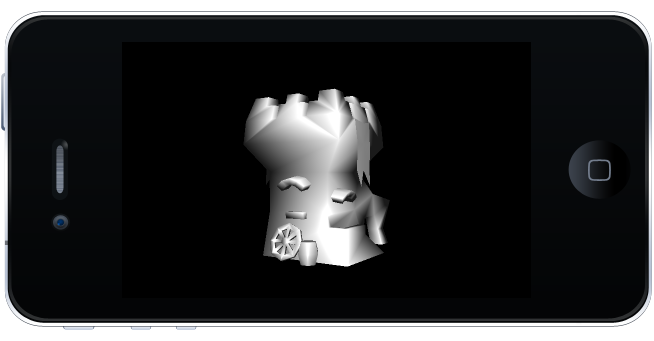
We are now going to add the contribution of the specular light. The specular light should provide a white highlight shining over the 3D model.
Modify line comment 22 to look like listing 14.
Listing 14. Specular light contribution
//22. add all the light components
return computeAmbientComponent()+computeDiffuseComponent(surfaceNormal)+computeSpecularComponent(surfaceNormal,surfacePosition);
Run the project. The characteristics of the 3D model are clearly defined with the addition of all three lights. A white highlight is also shown shining over the 3D model as it passes in front of the light.
Figure 3. Specular light contribution
Combining light and texture
We are almost done. Our project is capable of applying a texture to our 3D model. We are going to apply a texture to our 3D model and combine the lighting contribution to the texture.
Head over to line comment 38 and copy what is shown in listing 15.
We sample the texture in line 38. The texture sample color is assigned to the variable textureColor. This variable is mixed with the contribution from the lights, i.e., finalLightColor. (line 39).
Finally, line 40 outputs the final mixed color from the texture and the light.
Listing 15. Applying a texture
//38. Sample the texture using the Texture map and the texture coordinates
mediump vec4 textureColor=texture2D(TextureMap,vTexCoordinates.st);

//39. Mix the texture color and fragmentColor
mediump vec4 finalMixedColor=mix(textureColor,finalLightColor,0.3);

//40. set the final color to the output of the fragment shader
gl_FragColor = finalMixedColor;
Run the project. You should now see a 3D model with a texture and light shining over it.
Figure 4. Texture with light contribution

Source code
The final source code can be found here.
Questions?
So, do you have any questions? Is there something you need me to clarify? Did this project help you? Please let me know. Add a comment below and subscribe to receive our latest game development projects.
Note:
If you are using a newer Xcode version, you may get the following error:
"Couldn't decode the image. decoder error 29: first chunk is not the header chunk"
If you are getting this error message, the settings in Xcode is preventing the loading of png images.
To fix this, click on the project name, and select "Build Settings". Search for "Compress PNG Files". Set this option (debugger/Release) to NO.
Right below this option, you should see "Remove Text Metadata From PNG FIles". Set this option to NO.
When you build and run the project, the error mentioned above should go away and the png images should show up.
If you need more help, please visit my support page or contact me.
Update:
In newer Xcode versions, you may get this error while running the project demos:
"No such file or directory: ...xxxx-Prefix.pch"
This error means that the project does not have a PCH file. The fix is very simple:
In Xcode, go to new->file->PCH File.
Name the PCH file: 'NameOfProject-Prefix' where "NameOfProject" is the name of the demo you are trying to open. In the OpenGL demo projects, I usually named the projects as "openglesinc."
So the name of the PCH file should be "openglesinc-Prefix"
Make sure the file is saved within the 'NameOfProject' folder. i.e, within 'openglesinc' folder.
Click create and run the project.
