I know that you are desperate to render your first 3D object using the Metal API. However, computer graphics can be difficult to grasp in the beginning. To help you out, I wrote this article that talks about the major components in a rendering pipeline.
In this article, I'm going to explain the following concepts:
- Mesh
- Rendering Pipeline
- Attributes
- Uniforms
- Matrix Transformations
- Functions (Shaders)
- Framebuffer
Learning these concepts before you use the Metal API (Or OpenGL) will be beneficial.
What is a Mesh
A mesh is a collection of vertices, edges, and faces that define the shape of a 3D object. The most popular type of polygon mesh used in computer graphics is a Triangle Mesh. Any object, either a mountain or a game character, can be modeled with Triangle meshes.
For example, the image below shows triangle meshes making up a tank.

The vertices of a mesh are the inputs to a Rendering Pipeline. These vertices go through several stages, such as coordinate transformation and rasterization, before they end up in the framebuffer, i.e., the screen.
The Rendering Pipeline
The Rendering Pipeline are the stages that vertices must go through before appearing on the screen of your device. The GPU, not the CPU, is in charge of the rendering pipeline.
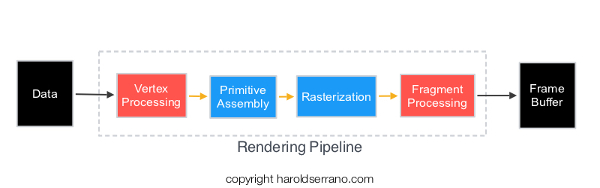
In general, the vertices of a mesh goes through the following stages in a rendering pipeline:
- Vertex Processing
- Primitive Assembly
- Rasterization
- Fragment Processing
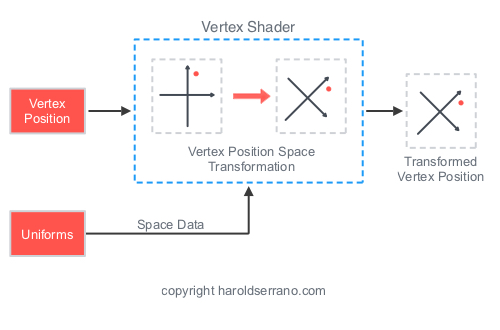
Vertex Processing
The Vertex Processing stage processes incoming geometrical data, i.e., vertices. In this step, each vertex coordinate system is transformed by a space matrix, thus changing the vertex original coordinate system to a new coordinate system.
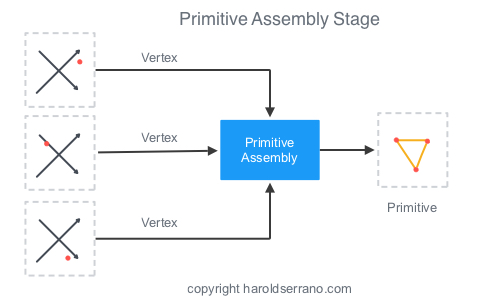
Primitive Assembly
The Primitive Assembly constructs a primitive using three processed vertices from the Vertex Processing stage.
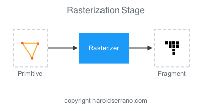
Rasterization
What you see on a screen are pixels approximating the shape of a primitive. This approximation occurs in the Rasterization stage. In this step, pixels are tested to determine if they are inside the primitive’s perimeter. If they are not, they are discarded.
If they are within the primitive, they are taken to the next stage. The set of pixels that passed the test is called a Fragment.
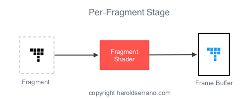
Fragment Processing
The responsibility of the Fragment Processing stage it to apply color or texture to the fragment.
Shaders
Long ago, the Rendering Pipeline was fixed. Meaning that a developer had no way to influence the outputs of any of the stages in the pipeline.
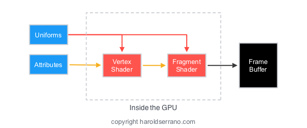
However, that is no longer the case. Today, you control the outputs of two stages in the pipeline; the Vertex Processing and Fragment Processing stages. These stages are controlled through GPU programs called "Shaders." In Metal, they are known as "Functions."
The GPU program that controls the Vertex Processing stage is known as a Vertex Shader. Whereas, the program that controls the Fragment Processing stage is known as a Fragment Shader.
Furthermore, you program these shaders with a special programming language called "Shading Languages". In OpenGL, the shading language is known as GLSL (or OpenGL Shading Language). In Metal, the shading language is called "Metal Shading Language."
Transformations
If you hate mathematics but love computer graphics, then you better start hating math a bit less. Mathematics, especially Linear Algebra, plays a huge role in computer graphics, games, graphics effects, etc.
In computer graphics, Matrices are used to transform the coordinate system of a mesh.
For example, to rotate a square 45 degrees as shown below requires a rotational matrix to transform the coordinate system of each vertex of the square.

Matrices are not only used to rotate a mesh, but also to create the illusion of 3D objects on a screen.
To render a 3D object, you are required to implement several transformations. For example, the coordinate space of a model is transformed by a view (camera) matrix. This new coordinate system is known as the Model-View coordinate system. And it shows the position of the model with respect to the camera.
A Projective-Perspective matrix further transforms the Model-View coordinate system, thus creating a 3D illusion. These set of transformation is known as the Model-View-Projection transformation.
Thus, if you want to display an object in 3D, the object must be transformed the by Model-View-Projection Matrix.
Attributes and Uniforms
Attributes
Elements that describe a mesh, such as vertices, are known as Attributes. Aside from vertices, Normal Vectors, and UV coordinates also define a mesh. Normal Vectors are vectors perpendicular to the vertices direction and are used to apply lighting to a model. UV coordinates are used for texturing.
An attribute is also defined as the input to a Vertex Shader (function). The Vertex Shader is the only stage that can receive attribute data from the CPU. The Fragment Shader can't receive attribute data directly from the CPU.
If the Fragment Shader needs attribute data, it must be passed down from the Vertex Shader.
Uniforms
A Vertex Shader deals with constant and non-constant data. An Attribute is data that changes per-vertex, thus non-constant. Uniforms are data that are constant during a render pass.
For example, if your mesh has six vertices, the Vertex Shader will process six different attributes during the render pass. However, it will process the same uniform data during the render pass.
Transformation matrices are usually sent as uniform data to the GPU.
Unlike attributes, both shaders can receive Uniform data.
Framebuffer
The destination of a rendering pipeline is a Framebuffer. A framebuffer contains several attachments such as Color, Depth, and Stencil attachments. However, a framebuffer can display the rendering content to a screen ONLY if a 2D array memory has been allocated and attached to a framebuffer attachment. A 2D array memory is known as a Texture image.

In Metal, you must ask the system for the next available texture which can be attached to the framebuffer.
Now that you know the basics of computer graphics, Metal or OpenGL will be a lot easier to understand. Metal and OpenGL are simply APIs that allow you to communicate with the GPU.
Click here to start using Metal.
Hope this helps


